
Feasibility Verification of GAI-Generated Data: Geometric Simulation, Mechanical Analysis, and Production Line Application
Introduction
In today’s landscape, where smart manufacturing has become the core competitive advantage of the industry, machining simulation and verification have evolved from auxiliary tools to critical components ensuring the reliability and efficiency of digital manufacturing. With the rapid popularization of automation and AI, the design of toolpaths and machining parameters is shifting from manual expertise toward algorithmic generation. While this significantly enhances design efficiency and innovation speed, it introduces a pivotal challenge: how to verify that automatically generated data can be executed safely on actual production lines while maintaining quality.
Without proper verification, risks such as tool damage, workpiece scrapping, and machine impairment arise—increasing costs, delaying deliveries, and eroding customer trust. This is particularly detrimental to small and medium-sized enterprises (SMEs) with limited resources. Consequently, machining simulation verification is no longer just a technical option; it is an urgent response to industrial demands for reducing trial-cutting costs, shortening implementation cycles, and ensuring stable quality.
Machining simulation technology enables toolpath inspection and interference/collision detection prior to actual cutting. By identifying potential risks in tool motion and material removal in advance, it reduces trial-and-error costs. As processes become increasingly complex, verification is essential not only for preventing collisions but also for ensuring efficiency and precision. Furthermore, cutting mechanics verification allows for the evaluation of tool load, spindle power, and machining stability before program execution, preventing chatter and quality degradation caused by improper parameters.
Machining Simulation Verification Technology
In the digital manufacturing workflow, Virtual Machining (VM) technology has become a key method for ensuring the feasibility of automated toolpaths. This technology simulates the actual cutting process—including tool motion, material removal, interference detection, and machine constraint verification—within a virtual environment. It effectively prevents risks such as collisions, gouging, and mechanical damage caused by path errors. Key feasibility verification indicators for generated data include gouge checking and tolerance inspection of the toolpath.
Currently, mainstream geometric removal technologies center on Z-Map and Dexel (Depth Pixel).
-
Z-Map: This is the earliest and most widely used geometric modeling technique for 3-axis machining simulation. The basic concept involves projecting the workpiece space onto a fixed-resolution XY grid, where each grid cell stores a Z-axis depth value representing the material surface height. This height is continuously updated during simulation to reflect material removal. As noted in the paper by Seung Ryol Maeng et al. regarding Z-map update methods for linear moving tools [1], the process is simulated by updating the Z-map vectors corresponding to the swept surface generated by the toolpath. When the tool’s rotation axis is parallel to the Z-axis, the Z-map is updated via the swept surface produced by the tool's bottom face. By calculating the intersection of the tool's swept surface and the Z-map vectors, the simulation updates the material state.
-
Advantages: Simple data structure, low memory footprint, and ease of updates. It is highly suitable for 2.5D or unidirectional machining simulations and is particularly popular for verifying toolpaths for large-scale molds.
-
Limitations: It cannot accurately simulate cutting behavior from the side or multiple directions, making it unsuitable for 5-axis machining simulations.
-
-
Dexel: To overcome these limitations and support multi-axis simulation, Dexel modeling was developed. According to Valentin et al. [2], Dexel modeling represents an object as a line network composed of three sub-networks aligned with the global X, Y, and Z axes. A Dexel is a 1D element representing a line segment within the object. Sub-networks are placed at discretized steps along the respective planes. During cutting simulation, when the tool passes through the workpiece area, the corresponding segments of the tri-directional Dexel rays are clipped or updated to simulate material removal, ensuring the simulation results closely align with actual machining outcomes.
However, geometric simulation via Z-Map or Dexel alone may overlook dynamic factors leading to mechanical interference and collision risks in complex 5-axis or high-speed milling. To enhance safety, anti-collision modules combining kinematics, solid collision detection, and path prediction have been developed. According to U.S. Patent US20160188770A1 [3], a method based on Multibody Kinematics models each machine component (e.g., spindle, table, rotary axis) as a movable rigid body to simulate motion based on NC path data. This allows for full-time collision checking between the tool model and the machine structure. If potential interference occurs at any point, the system provides an immediate alert or automatically corrects the path. The patent also reveals a visual feedback mechanism where potential interference zones are highlighted on the simulation interface, allowing users to adjust paths proactively.
Integrating Dexel or Z-Map geometric models with these kinematic dynamic simulations and collision detection algorithms creates a predictive, proactive digital manufacturing environment, ensuring all risks are eliminated before complex multi-axis tasks are executed in reality.
Geometric Topology Verification Technology
To verify the geometric consistency between the machining simulation results and the original CAD target part, a Raytracing-based comparison method can be employed. By inspecting the geometric accuracy of the simulation results against set tolerances, it serves as a feasibility verification indicator for the generated data.
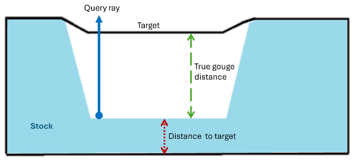
This technique utilizes a Render Mode for visual comparison. The core concept involves casting a ray from every visual pixel; when a ray hits the geometric boundary of the target part, the distance to the simulated "stock" model surface is calculated and visualized via Color Mapping.
Users can define several tolerance intervals and assign corresponding colors. For example:
-
Undercut (Blue): The stock surface exceeds the target model by more than 0.01 units.
-
In Tolerance (Green): The distance is within ±0.01 units, indicating good precision.
-
Gouge (Red): The stock surface enters the target model by more than 0.01 units.
Figure 1 illustrates a geometric comparison case using Ray Tracing. The black outline represents the CAD target geometry, while the blue area represents the stock generated by simulation. A query ray is cast from a point on the stock surface to intersect with the target geometry. If the intersection point exceeds the preset tolerance (0.01 units in this case), a gouge is identified.
 |
Cutting Mechanics Verification Technology
Verifying whether GAI-generated toolpaths are reasonable and safe is a critical hurdle for industrial adoption. Cutting mechanics verification plays a vital role here. Although international standards for GAI-generated data verification are not yet established, the field of metal cutting already possesses robust offline physical simulations and online quality monitoring technologies. These methods ensure that AI-generated paths are not only innovative but also highly usable.
First, for toolpath generation, offline simulation and specific cutting force models can be used to check GAI paths segment by segment. This predicts potential overloads, excessive tool tip deflection, or spindle power limits, allowing unreasonable paths to be filtered out automatically.
Second, for machining parameter generation, GAI proposes combinations of feed rate, depth of cut, and width of cut based on historical data. However, differences in material and machine rigidity can introduce risks. Cutting mechanics verification can check these parameters in real-time to determine if they cause excessive force, chatter, or shortened tool life. This creates a "Generation–Verification–Correction" loop, making GAI parameters more engineering-ready and compliant with actual manufacturing conditions
1. Offline Physical Simulation Verification
Current cutting mechanics verification methods fall into three categories. The first is offline physical simulation, which uses mathematical models to predict cutting forces, spindle power, and tool tip deflection before the NC program is executed. These methods often adopt the general milling mechanics model proposed by Engin and Altintas [5], combined with the Kienzle–Victor relationship [6], to estimate the main cutting force as shown in Equation (1):
 (1)
(1)
Where $F_c$ is the main tangential force, $k_c$ is the specific cutting force constant per unit thickness, $h$ is the uncut chip thickness, $m$ is the material-dependent index, and $b$ is the contact width of the cutting edge. This model allows for rapid force prediction across various materials and cutting scenarios.
In commercial applications, high-end CAM software and Digital Twin solutions—such as Siemens NX Machining, Autodesk PowerMill, and ModuleWorks Cutting Simulation [4]—feature built-in mechanics verification modules. Sandvik CoroGuide provides parameter optimization based on tool catalogs [7], while machine tool manufacturers like DMG MORI (CELOS) and Mazak (Smooth Ai) integrate real-time monitoring and AI prediction into their digital twin solutions.
2. Dynamics and Stability Verification
Dynamics and stability verification involve establishing a dynamic model of the "tool-workpiece-machine" system to analyze chatter tendencies and plot Stability Lobe Diagrams (SLD) [8]. In metal cutting, even if cutting forces are within static limits, chatter can cause poor surface roughness, tool chipping, and scrapped parts. The core approach involves measuring the Frequency Response Function (FRF) to obtain dynamic stiffness and damping characteristics. The resulting SLD reveals the critical depth of cut at different spindle speeds. If GAI-generated parameters fall within the stable zone of the SLD, the combination is verified as feasible.
Commercial products like CutPro (MAL Inc.) provide comprehensive modules for FRF measurement and SLD calculation. This technology is vital for GAI integration, as it links AI outputs with actual machine dynamic behavior, reducing scrap rates and extending tool life, especially in high-risk tasks like thin-wall milling.
3. Online Monitoring Methods
Online monitoring utilizes sensors to collect real-time data—including cutting force, vibration, spindle current, and acoustic features. Features are extracted via Fast Fourier Transform (FFT) or wavelet analysis to identify tool wear, chatter, or breakage [9].
In a GAI context, online monitoring creates a closed data loop: by comparing actual cutting data with AI-predicted values, the system can provide real-time feedback. If errors exceed a threshold, the system corrects parameters immediately to ensure safety. Statistical analysis (e.g., the Cpk process capability index) can further evaluate the impact of AI parameters on long-term stability. Commercial examples include Sandvik CoroPlus Process Control [10] and Mazak SMOOTH Technology [9], which can trigger emergency stops or parameter adjustments to prevent workpiece loss.
4. Adaptive Control and Model Calibration
Adaptive Control and Model Calibration dynamically adjust parameters based on sensor data. This involves three layers: sensor data collection, algorithmic adjustment of feed/speed, and model calibration to ensure accuracy as tools wear [6][11].
For GAI verification, this enables a "dynamic verification" mechanism. If monitoring data exceeds model limits, the system reduces the feed rate to avoid overload. If the calibrated model error stays low (e.g., Mean Squared Error < 2%), the parameter's rationality is confirmed. Specific verification items include:
-
Tool Overload Evaluation: Predicting forces to ensure they don't exceed spindle power.
-
Chatter Evaluation: Ensuring parameters stay within the SLD stable zone.
-
Tool Tip Deflection Limits: Verifying deflection stays below critical values for quality control [5].
-
Real-time Anomaly Detection: Using AI or statistical methods (Cpk) to ensure machining safety.
Commercial cases such as Fanuc iAdapt S [12] and Okuma Machining Navi [13] have pushed cutting mechanics verification from academia to industrial standard.
Conclusion
The development of machining simulation and verification is evolving from simple geometric checks toward a multi-layered integration of mechanics, dynamics, and intelligent monitoring. This evolution not only meets the requirements for implementing GAI on the shop floor but also provides a complete solution with predictive and self-correcting capabilities.
For Taiwan’s SMEs, applying these technologies can reduce trial-cutting costs, extend tool life, and build smart manufacturing capabilities aligned with international standards. In the future, as more GAI technologies enter production lines, simulation verification will transition from an "optional feature" to an essential foundation for the safe and efficient operation of digital factories. In short, machining simulation verification has become an indispensable player in the journey of industrial digital transformation.
參考文獻
- S. R. Maeng, N. Baek, S. Y. Shin, B. K. Choi,“A Z-map update method for linearly moving tools,” Computer-Aided Design, 35(11), 995-1009, 2003.
- V. Dambly, É. R. Lorphèvre , O. Verlinden, “Tri-dexel based cutter-workpiece engagement determination for robotic machining simulator. Procedia CIRP,”107, 1059-1064, 2022.
- N. Montana, R. Nosenzo, “Simulating the machining of a workpiece,” US 20160188770 A1, 2016.
- MachineWorks Ltd., “Simulation Guide Volume 1,” 8.6, 183, 2024.
- S. Engin, Y. Altintas, “Mechanics and dynamics of general milling cutters, Part I: Helical end mills,”Int. J. Mach. Tools Manuf., 41, 2195–2212, 2001.
- German Copper Institute ,“Recommended machining parameters for copper and copper alloys,” DKI Monograph i.18, 15, 2010, [Online]. Available: https://www.copper.org/applications/marine/cuni/pdf/DKI-Machining.pdf?utm_source=chatgpt.com
- Sandvik Coromant,“CoroPlus Process Control - Monitor machining processes and automate actions,” [Online]. Available: https://pdf.directindustry.com/pdf/sandvik-coromant/coroplus-processcontrol/14460-991142.html
- Y. Altintas, E. Budak,“Analytical prediction of stability lobes in milling,” CIRP-IJMTM, 44(1), 357–362, 1995.
- Mazak Corp., [Online]. Available: https://www.mazak.com/us-en/technology/machining-technology/
- Sandvik Coromant, “Sandvik CoroPlus Tool Guide,” [Online]. Available: https://www.sandvik.coromant.com/en-us/tools/digital-machining/coroplus-tool-guide?utm_source=chatgpt.com
- P. L. B. Oxley, “The Mechanics of Machining: An Analytical Approach to Assessing Machinability,”
Ellis Horwood, 1989. - Automation.com,“FANUC integrates iAdaptS controller into CNC,” [Online].
Available: https://www.automation.com/en-us/products/product13/fanuc-integrates-iadapts-controller-into-cnc?utm_source=chatgpt.com - Okuma Corporation, “Machining Navi - Intelligent Technology,”[Online]. Available: https://www.okuma.co.jp/english/onlyone/process


