
Exploration of Cradle-Type Tilting Axis Positioning Accuracy Measurement for Tsudakoma
Using an angular swing inspection instrument (API Swivel Check), this article shares the actual measurement results of the positioning accuracy of Tsudakoma’s tilting axis, analyzing the accuracy differences when the angle encoder is enabled versus disabled. A 1° incremental measurement method is adopted to explore the operational characteristics of this mechanical structure.
Five-axis machine tools are widely used in aerospace, medical devices, automotive, and mold manufacturing. As consumer demand for precision increases, machine tool quality must continuously improve. The flexibility, high precision, and efficiency of five-axis machines make them indispensable in modern manufacturing.
Advances in technology and software/hardware development have made programming and operating five-axis machines easier. These machines offer multiple degrees of freedom, allowing tools to follow specific angles (RTCP – Rotated Tool Center Point), reducing the need for multiple setups, high-precision fixtures, and different machines, thereby improving surface quality and reducing costs. Large workpieces such as molds and structural frames typically require horizontal or gantry-type spindle rotation and tilt, while small components like turbine blades, gears, artificial joints, small molds, watches, or jewelry are better suited for vertical rotary-tilt tables.
International Standard Definition
According to ISO 230-1, five-axis machine errors include 21 linear axis errors and 22 rotary axis errors, defined as component errors and location errors. For three-axis machines, there are 18 component errors plus 3 assembly location errors (total 21). Adding two rotary axes (commonly B and C or A and C) introduces 6 component errors and 5 location errors per tilt axis, totaling 22 rotary errors. Combined with the original 21, a five-axis machine has 43 error items.
 |
Sources of Tilting Axis Errors
Errors during rotary table tilt motion can result from poor assembly, dynamic deformation due to cutting forces, transmission accuracy, wear-induced backlash, static deformation under load, bearing precision, and thermal deformation.
 |
Measurement Focus
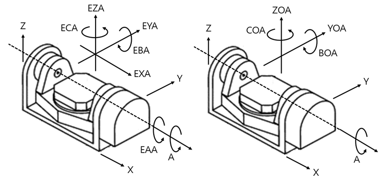
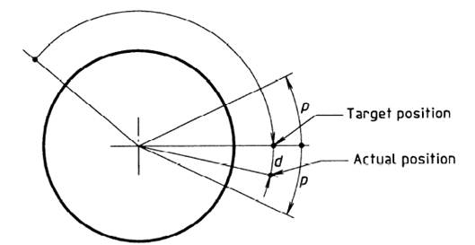
This study measures EAA error, defined as the deviation of a point after rotation around the tilt axis from its target position. The deviation (d) is the distance between actual and target positions, and angular displacement tolerance is p. ISO defines EAA as including angular errors (EBA, ECA) and axial deviations (EXA, EYA, EZA).
 |
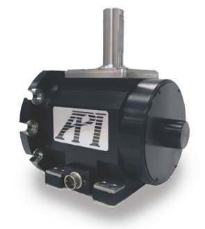
Angular Swing Inspection Instrument
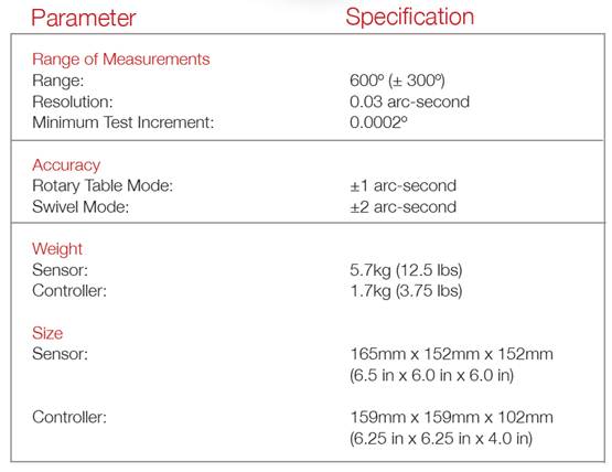
The instrument measures in arc-seconds (1/3600°), with a range of 600°, resolution of 0.03 arc-sec, and minimum increment of 0.0002°. Environmental temperature and humidity must remain within 5% variation. Proper alignment and signal integrity are critical for accurate results.
 |
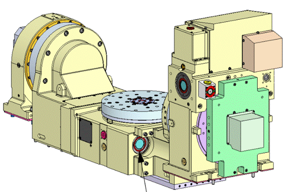
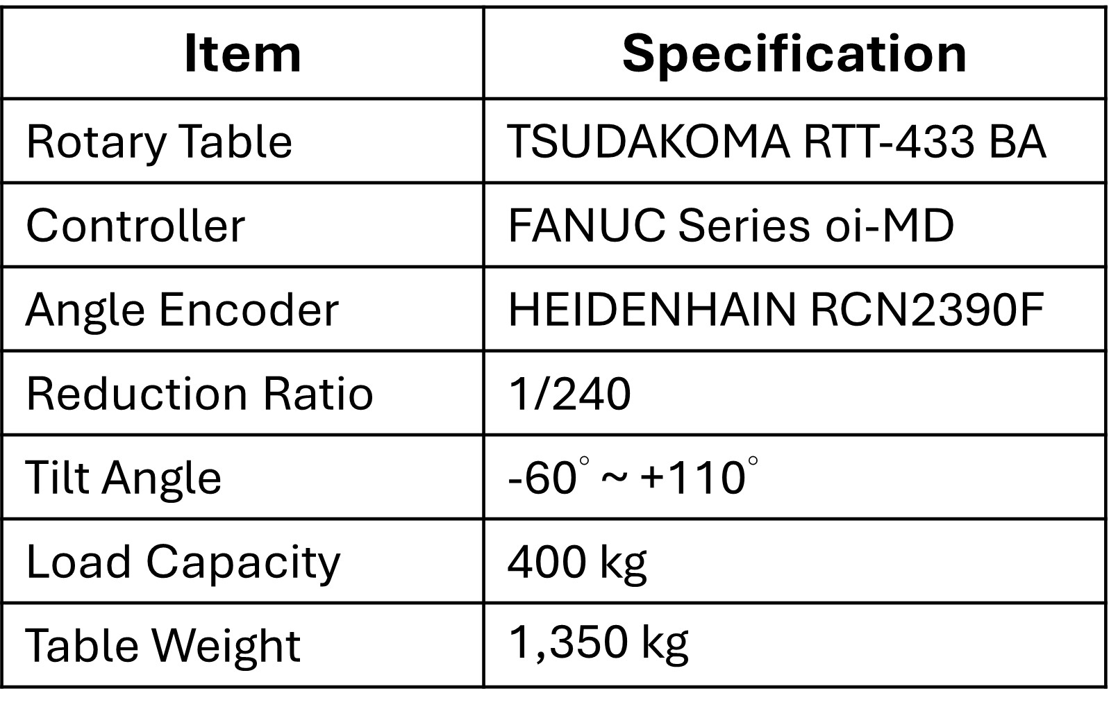
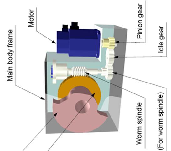
Tsudakoma RTT-433 BA Tilting Axis Module
This cradle-type rotary module, widely adopted for high-end machines, uses angle encoders to enhance positioning and repeatability by directly measuring the rotary axis rather than relying on motor signals. Specs:
- Tilt angle: -60° to +110°
- Reduction ratio: 1/240
- Load capacity: 400 kg
- Module weight: 1350 kg
- Encoder: HEIDENHAIN RCN2390F
- Controller: FANUC Series oi-MD
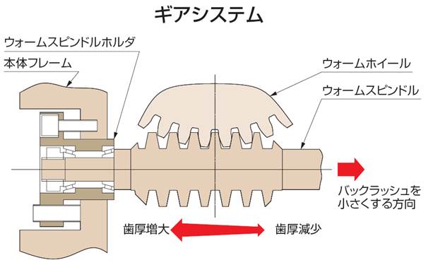
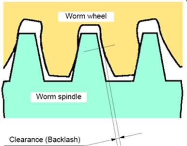
Transmission uses a dual-lead worm gear for high strength, efficiency, and adjustable backlash.
|
Figure 4. Tsudakoma RTT-433 BA |
Figure 5. Dual-lead worm gear structure |
 |
 |
 |
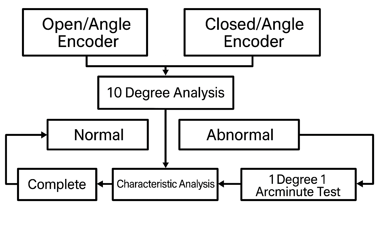
Inspection Process
Measurements compare encoder ON vs OFF:
- Initial 10° increments
- If anomalies occur, perform 1° incremental checks
- Analyze and compensate errors
 |
Results
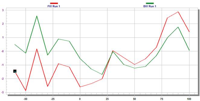
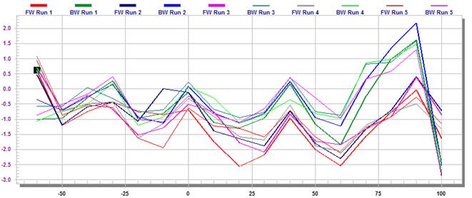
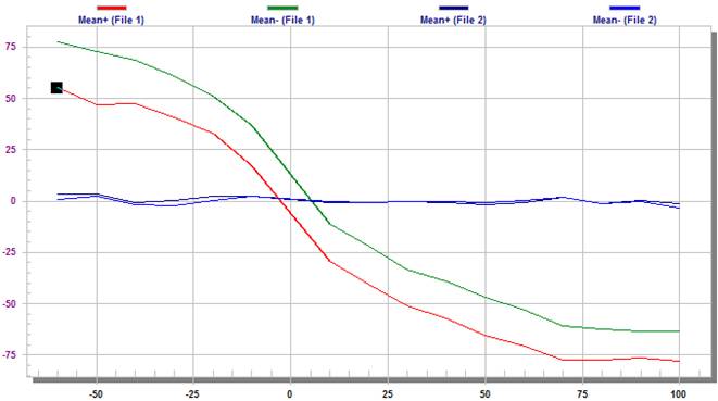
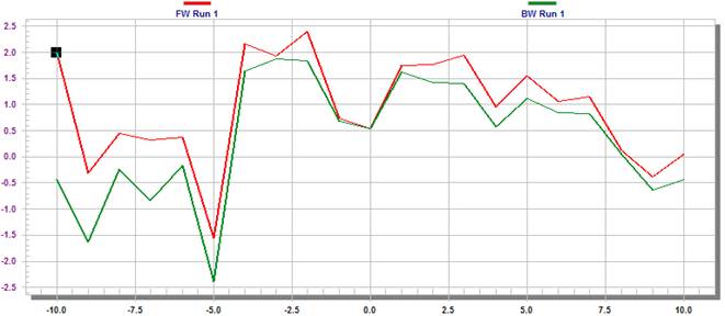
- Encoder ON: Initial error 5.7 arc-sec, improved to 4.7 arc-sec after compensation; path overlap 85%.
| Figure 7: Encoder ON – Before compensation: 5.7 arc-sec | Figure 8: Encoder ON – After compensation: 4.7 arc-sec | Figure 9: Encoder ON – Path overlap rate after compensation: 85% |
 |
 |
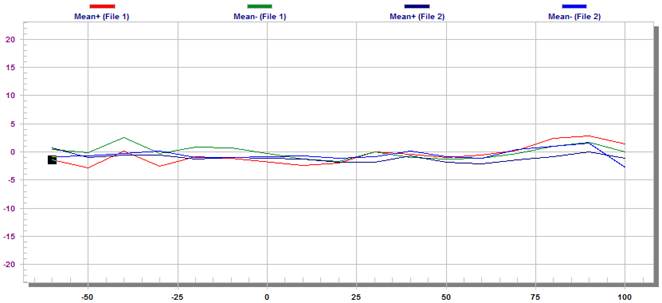 |
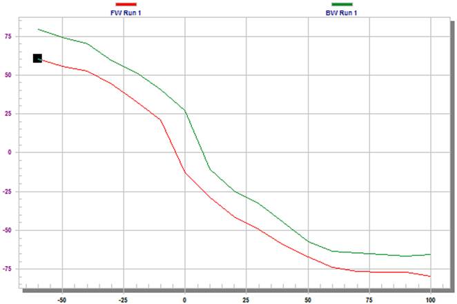
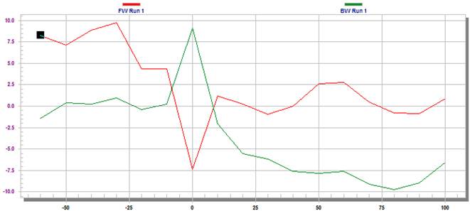
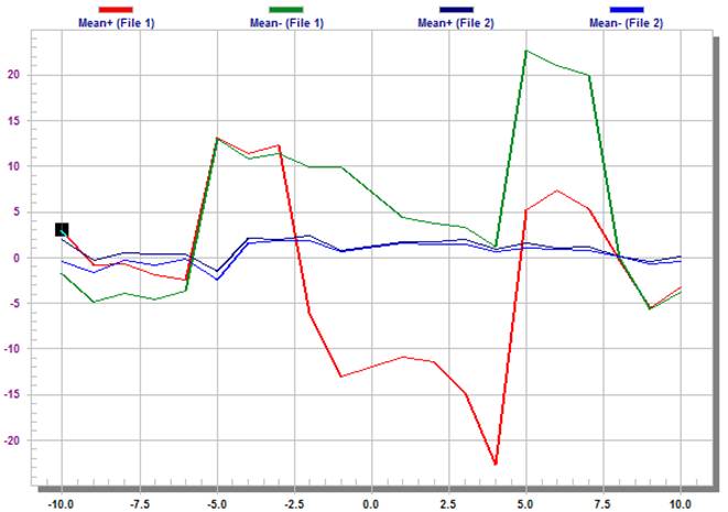
- Encoder OFF: Initial error 155 arc-sec, improved to 19 arc-sec after compensation (87% improvement), but anomalies persist near ±10° range. Detailed 1° checks reveal 45 arc-sec error ignored by 10° increments.
|
Figure 10: Encoder OFF – Before compensation: 155 arc-sec |
Figure 11: Encoder OFF – After compensation: 19 arc-sec |
 |
 |
|
Figure 12: Encoder OFF – Error improvement: 87% |
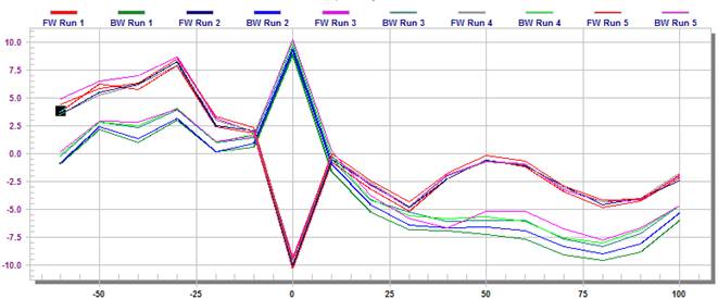
Figure 13: Encoder OFF – Five-pass positioning accuracy after compensation |
 |
 |
|
Figure 14: Encoder OFF – ±10° range error: 45 arc-sec |
|
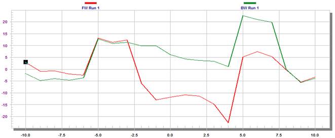 |
- Comparison: Encoder ON shows only 4 arc-sec error in ±10° range, confirming encoder significantly improves accuracy and mitigates structural limitations.
|
Figure 15: Encoder ON – ±10° range error: 4 arc-sec |
Figure 16: Comparison of encoder ON vs OFF with 1° incremental measurement |
 |
 |
Discussion
Large errors near ±10° without encoder are due to cradle mechanics and shifting center of gravity, especially near 0°, where bearing contact changes under inertia. This non-linear behavior is hard to predict and prominent in this Tsudakoma model.
| Figure 17. Internal structure of the tilting axis | Figure 18. Influence of center of gravity and inertia on bearing contact position |
 |
 |
Conclusion
Using API Swivel Check, this study confirms that enabling angle encoders greatly enhances positioning accuracy and repeatability. The 1° incremental method is highly recommended for analyzing structural characteristics and controller compensation capabilities, providing valuable insights for machine development. Domestic manufacturers should leverage these findings to improve machine precision and competitiveness.


