
Overview of Accuracy Measurement for Domestic Five-Axis Machine Tools: A Case Study on Moving Column Cradle-Type
By Precision Machinery Research & Development Center, Verification Technology Development Department – Engineers Chen Ke-Rui, Wu Xiang-Ru
Five-axis machining centers offer high flexibility, enabling the processing of complex workpieces while reducing fixture changes and downtime. This improves machining efficiency, shortens production time, and extends tool life. Today, five-axis machines are indispensable for manufacturing high-precision, high-quality components.
Impact of Geometric Accuracy and Performance
The geometric accuracy and performance of machine tools significantly affect machining quality. In this study, the Precision Machinery Center measured the spatial accuracy of newly manufactured five-axis machines from domestic manufacturers. A total of 27 machines were tested:
- 13 moving-column type
- 9 gantry type
- 5 double-column type
The inspection items included:
- Linear axis six degrees of freedom errors
- Rotary axis positioning accuracy
- Circular interpolation tests
- 3D spatial diagonal analysis
- R-Test for tool-tip synchronous motion accuracy
Reference standards and instruments are summarized in Table 1.
Table 1: Accuracy Measurement Items and Reference Standards
| Item | Error Evaluation | Standard | Instrument |
|---|---|---|---|
| 1 | Linear axis 6 DOF errors (X, Y, Z) | ISO 10791-2 | Renishaw XM-60 (6D Laser) |
| 2 | Rotary axis positioning accuracy (Swing axis, C-axis) | ISO 10791-4 | Renishaw XL-80, XR-20 |
| 3 | Circular interpolation (Roundness, Perpendicularity) | ISO 10791-6, ISO 230-4 | Renishaw QC-20 |
| 4 | 3D spatial diagonal analysis (4 diagonals) | ISO 230-6 | Renishaw XL-80 |
| 5 | Synchronous motion accuracy (DBB, IBS tool-tip tracking) | ISO 10791-6 | IBS R-Test |
Machine Configurations and Angular Error Definitions
Five-axis machines generally fall into three categories:
- Two rotary axes on the spindle head (Head-Head)
- Two rotary axes on the table (Table-Table)
- One rotary axis on the head and one on the table (Head-Table)
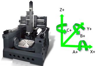
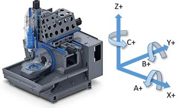
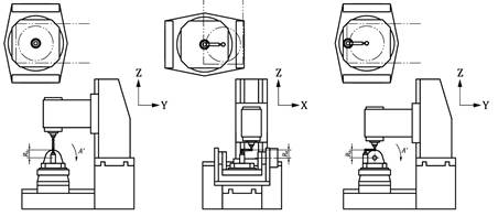
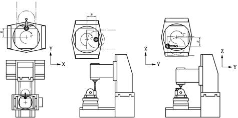
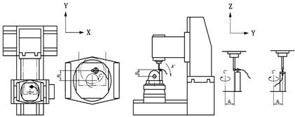
Moving-column and gantry types belong to the Table-Table configuration. For moving-column machines:
- Swing axis rotates about Y-axis (B-axis)
- Rotary axis rotates about Z-axis (C-axis)
Axes: X, Y, Z, B, C
| Figure 1. Moving-Column Five-Axis Machine Structure | Figure 2. Gantry-Type Five-Axis Machine Structure |
 |
 |
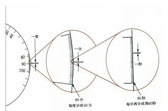
Angular errors are expressed in arc-seconds:
- 1° = 60 arc-minutes
- 1 arc-minute = 60 arc-seconds
- 1° = 3600 arc-seconds (~0.000278° per arc-second)
| Figure 3. Definition of Arc-Seconds | Figure 4. Definition of Arc-Seconds |
 |
 |
Standards and Test Data Analysis
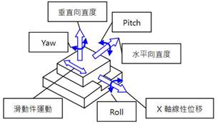
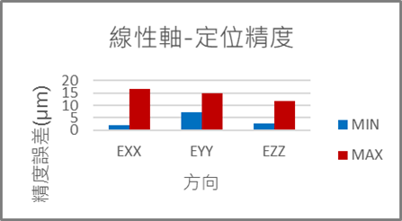
3.1 Linear Axis Six Degrees of Freedom
Each linear axis has six error components:
- Pitch, Yaw, Roll (angular errors)
- Horizontal straightness, Vertical straightness, Positioning accuracy
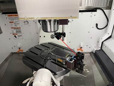
| Figure 5. Six Degrees of Freedom Errors for a Single Linear Axis | Figure 6. XM-60 Measuring the Y-Axis on a Five-Axis Machine |
 |
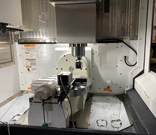 |
Measurements used Renishaw XM-60, following ISO 10791-2 (2023) standards.
Results:
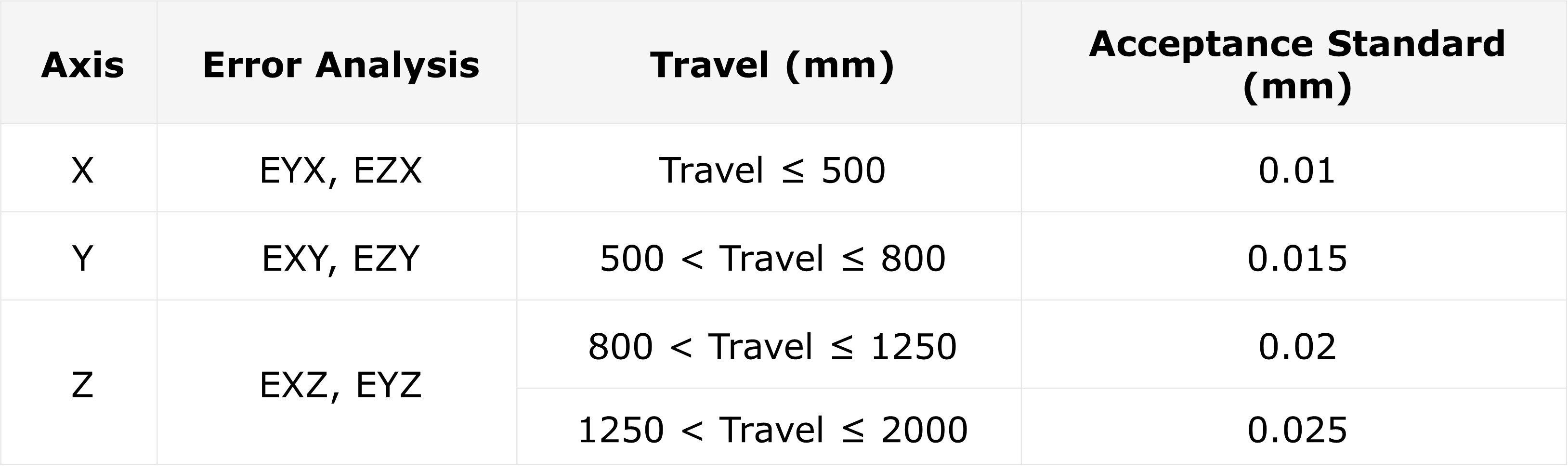
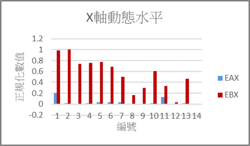
- Positioning accuracy: EXX max ~17µm, min ~2µm; EYY max ~15µm; EZZ max ~12µm
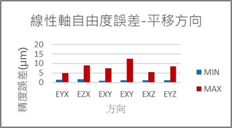
- Translation errors: EZY max ~13µm; EXY min ~1µm
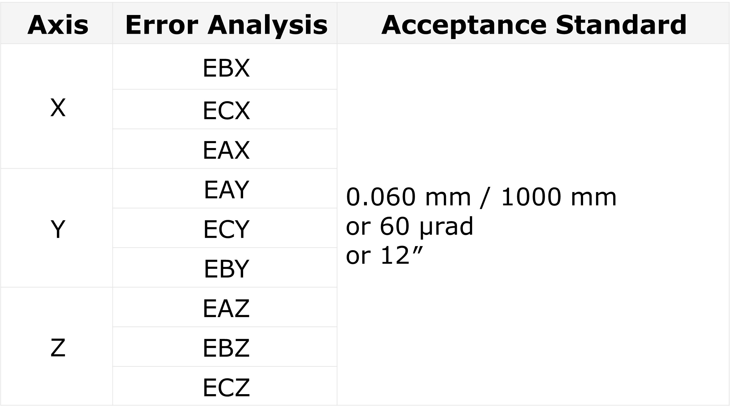
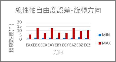
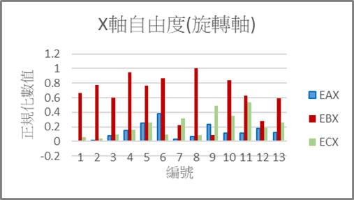
- Angular errors: EBX max ~13″; EAX min ~1″; EBY max ~8″; EAZ max ~13″
X-axis errors were larger due to structural mass and inertia.
 |
 |
| Figure 7. Single-Axis Degree of Freedom Error – Positioning Accuracy | Figure 8. Single-Axis Degree of Freedom Error – Translational Direction | Figure 9. Single-Axis Degree of Freedom Error – Rotational Direction |
 |
 |
 |
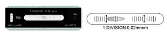
| Figure 10. X-Axis Single-Axis Degree of Freedom Error – Rotational Direction | Figure 11. Worktable Dynamic Level Test Result – X Direction |
 |
 |
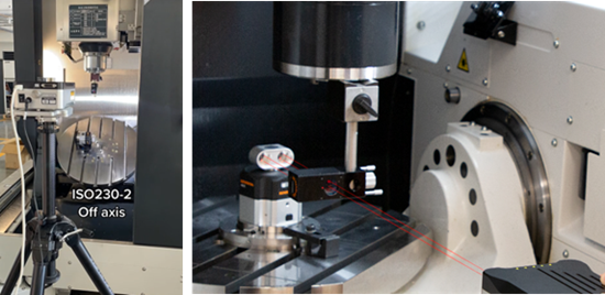
3.2 Rotary Axis Positioning Accuracy
Measured with Renishaw XL-80 & XR-20, per ISO 230-2.
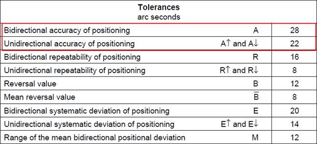
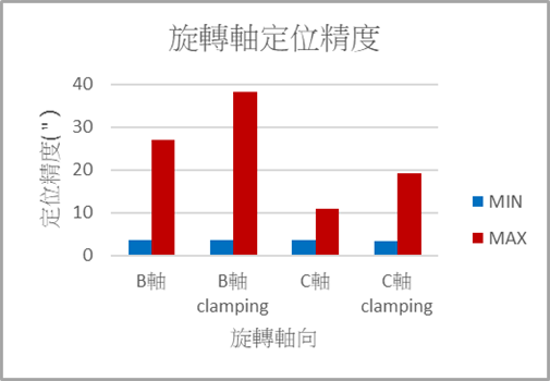
- C-axis error within 20″ (with or without clamping)
- B-axis error:
- Without clamping: max ~27″
- With clamping: max ~38″
Recommendation: Adjust brake system if clamping error is excessive.
| Figure 12. Rotary Axis Positioning Measurement Diagram | Figure 13. ISO 10791-4 Rotary Axis Positioning Accuracy Error Range | Figure 14. Rotary Axis Positioning Accuracy Error Data Chart |
 |
 |
 |
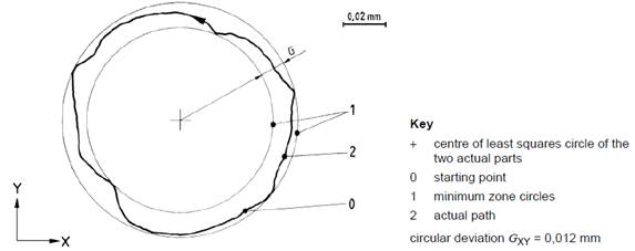
3.3 Circular Interpolation Test
Using Renishaw QC-20, per ISO 10791-6.
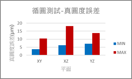
Results:
- Roundness error within 30µm
- XY plane best performance (max ~10µm), followed by XZ (~18µm) and YZ (~14µm)
| Figure 15. ISO 230-4 Definition of Roundness Error | Figure 16. Circular Interpolation Error Data Chart |
 |
 |
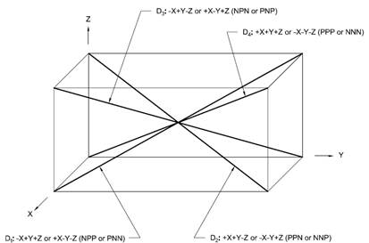
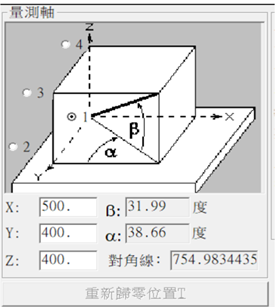
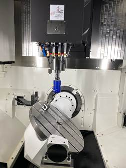
3.4 3D Spatial Diagonal Analysis
Using Renishaw XL-80, per ISO 230-6.
 ……(1)
……(1)
 ……(2)
……(2)
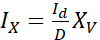 ……(3)
……(3)
Id: Diagonal Single-Step Displacement Distance
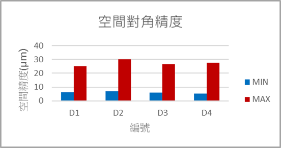
Results:
- All diagonal errors within 30µm
- D1 max ~25µm; D2 max ~30µm; D3 max ~27µm; D4 max ~28µm
| Figure 17. Spatial Diagonal Accuracy Measurement Diagram | Figure 18. ISO 230-6 Definition of Spatial Diagonal Accuracy | Figure 19. ISO 230-6 Measurement Path Planning |
 |
 |
 |
 |
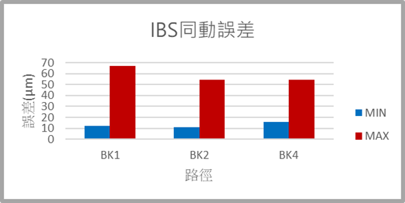
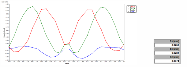
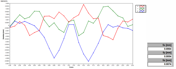
3.5 Tool-Tip Synchronous Motion Accuracy
Measured with IBS R-Test, per ISO 10791-6 paths (BK1, BK2, BK4).
 |
| Figure 22. BK1 Tool-Tip Synchronous Motion Path | Figure 23:.BK2 Tool-Tip Synchronous Motion Path | Figure 24: BK4 Tool-Tip Synchronous Motion Path |
 |
 |
 |
Results:
- BK1 max error ~67µm; BK2 ~54µm; BK4 ~54µm
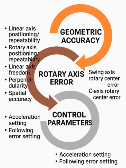
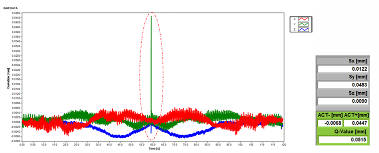
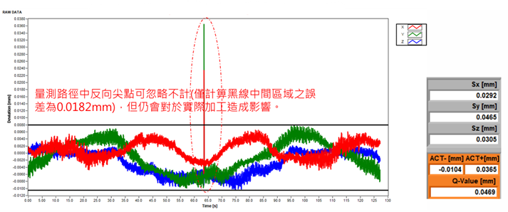
Errors mainly due to geometric accuracy, rotary center misalignment, and control parameters.
Compensation and parameter tuning significantly iproved accuracy (e.g., BK1 reduced from 126.3µm to 11.05µm after compensation).
| Figure 25. Tool-Tip Synchronous Motion Error Data Chart | Figure 26. Analysis of Causes for Tool-Tip Synchronous Motion Errors |
 |
 |
| Figure 27. BK1 Static Synchronous Motion Error – Original State | Figure 28. BK1 Static Synchronous Motion Error – After Rotary Center Compensation | Figure 29. BK1 Dynamic Synchronous Motion Error |
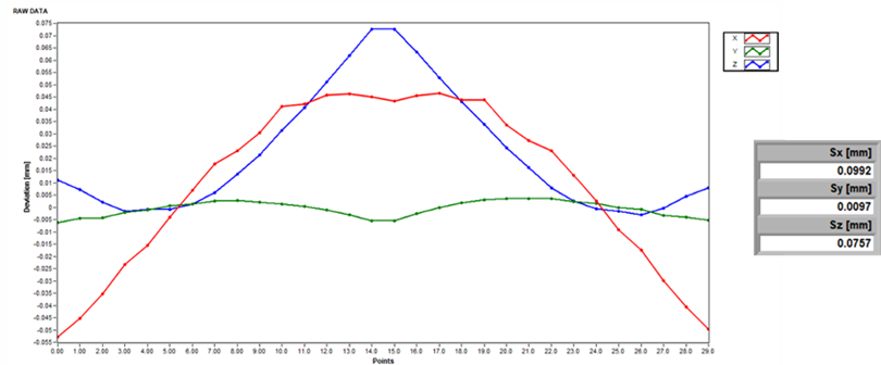 |
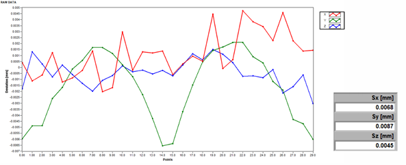 |
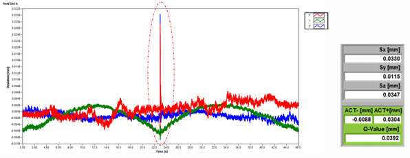 |
| Figure 30. BK2 Static Synchronous Motion Error – Original State | Figure 31. BK2 Static Synchronous Motion Error – After Rotary Center Compensation | Figure 32. BK2 Dynamic Synchronous Motion Error |
 |
 |
 |
 |
Conclusions
- Most domestic five-axis machines meet ISO 10791 standards; some achieve half the tolerance limits.
- Large clamping vs. unclamping error differences suggest brake system checks.
- For tool-tip synchronous tests, measure BK1 and BK2 first, then BK4.
- These findings can guide manufacturers in setting precision targets for future designs.
References
ISO 230 series, ISO 10791 series, technical bulletins from Precision Machinery Center.


